Verilog
Chap 2 Combinational Logic Circuits⚓︎
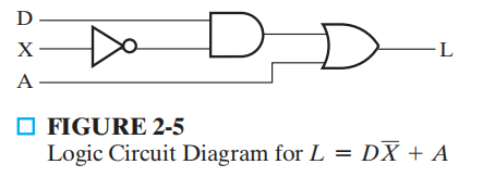
module fig2_5(L, D, X, A);
    input D, X, A;
    output L;
    wire X_n, t2;

    not (X_n, X);
    and (t2, D, X_n);
    or (L, t2, A);
endmodule
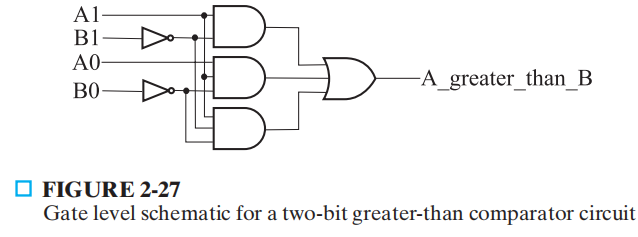
// structral model
module comparator_greater_than_structural(A, B, A_greater_than_B);
    input [1: 0] A, B;
    output A_greater_than_B;
    wire B0_n, B1_n, and0_out, and1_out, and2_out;

    not
        inv0(B0_n, B[0]), inv1(B1_n, B[1]);
    and
        and0(and0_out, A[1], B1_n);
        and1(and1_out, A[1], A[0], B0_n);
        and2(and2_out, A[0], B1_n, B0_n);
    or
        or0(A_greater_than_B, and0_out, and1_out, and2_out);
endmodule

// dataflow model
module comparator_greater_than_dataflow(A, B, A_greater_than_B);
    input [1: 0] A, B;
    output A_greater_than_B;
    wire B0_n, B1_n, and0_out, and1_out, and2_out;

    assign B1_n = ~B[1];
    assign B0_n = ~B[0];
    assign and0_out = A[1] & B1_n;
    assign and1_out = A[1] & A[0] & B0_n;
    assign and2_out = A[0] & B1_n & B0_n;
    assign A_greater_than_B = and0_out | and1_out | and2_out;
endmodule

// conditional model 1
module comparator_greater_than_conditional2(A, B, A_greater_than_B);
    input [1: 0] A, B;
    output A_greater_than_B;

    assign A_greater_than_B = (A > B)? 1'b1 : 1'b0;
endmodule

// conditional model 2
module comparator_greater_than_conditional(A, B, A_greater_than_B);
    input [1: 0] A, B;
    output A_greater_than_B;

    assign A_greater_than_B = (A == 2'b00) ? 1'b0 :
                (A == 2'b01)? ~(B[1] | B[0]) :
                (A == 2'b10)? ~B[1] :
                (A == 2'b11)? ~(B[1]&B[0]) :
                1'bx;
endmodule

// behavioral model
module comparator_greater_than_behavioral(A, B, A_greater_than_B);
    input [1: 0] A, B;
    output A_greater_than_B;

    assign A_greater_than_B = A > B;
endmodule

// testbench
module comparator_testbench_verilog();
    reg [1: 0] A, B;
    wire struct_out;
    comparator_greater_than_structural U1(A, B, struct_out);

    initial begin
        A = 2'b10;
        B = 2'b00;
        #10;
        B = 2'b01;
        #10;
        B = 2'b10;
        #10;
        B = 2'b11;
    end
endmodule
Chap 3 Combinational Logic Design⚓︎
2-4 译码器
module decoder_2_to_4_v(EN, A0, A1, D0, D1, D2, D3);
    input EN, A0, A1;
    output D0, D1, D2, D3;

    assign D0 = EN & ~A1 & ~A0;
    assign D1 = EN & ~A1 & A0;
    assign D2 = EN & A1 & ~A0;
    assign D3 = EN & A1 & A0;

endmodule;
4-1 多路选择器
module multiplexer_4_to_1_v(S, I, Y);
    input [1: 0] S;
    input [3: 0] I;
    output Y;

    assign Y = S[1] ? (S[0] ? I[3] : I[2]) : (S[0] ? I[1] : I[0]);

endmodule
4 位行波加法器
module half_adder_b(x, y, s, c);
    input x, y;
    output s, c;

    assign s = x ^ y;
    assign c = x & y;
endmodule;

module full_adder_v(x, y, z, s, c);
    input x, y, z;
    output s, c;

    wire hs, hc, tc;

    half_adder_v HA1(x, y, hs, hc), HA2(hs, z, s, tc);
    assign c = tc | hc;

endmodule;

module adder_4_v(B, A, C0, S, C4);
    input [3: 0] B, A;
    input C0;
    output [3: 0] S;
    output C4;
    wire [3: 1] C;

    full_adder_V Bit0(B[0], A[0], C0, S[0], C[1]),
                 Bit1(B[1], A[1], C[1], S[1], C[2]),
                 Bit2(B[2], A[2], C[2], S[2], C[3]),
                 Bit3(B[3], A[3], C[3], S[3], C[4]);

    // Or just one statement
    // assign {C4, S} = A + B + C0;

endmodule
Chap 4 Sequential Circuits⚓︎
正边沿触发器 ( 有复位功能 )
module dff_v(CLK, RESET, D, Q);
    input CLK, RESET, D;
    output Q;
    reg Q;

always @(posedge CLK or posedge RESET) begin
    if (RESET)
        Q <= 0;
    else
        Q <= D;
end
endmodule
module seq_rec_v(CLK, RESET, X, Z);
    input CLK, RESET, X;
    output Z;
    reg [1: 0] state, next_state;
    parameter A = 2'b00, B = 2'b01, C = 2'b10, D = 2'b11;
    reg Z;
// state register: implement positive edge-triggered
// state storage with asychronous reset
always @(posedge CLK or posedge RESET) begin
    if (RESET)
        state <= A;
    else
        state <= next_state;
end
//.te function: implements next state as function of X and state
always @(X or state) begin
    case (state)
        A: next_state = X ? B : A;
        B: next_state = X ? C : A;
        C: next_state = X ? C : D;
        D: next_state = X ? B : A;
    endcase
end
// output function: implements output as function of X and state
always @(X or state) begin
    case (state)
        A: Z = 1'b0;
        B: Z = 1'b0;
        C: Z = 1'b0;
        D: Z = X ? 1'b1 : 1'b0;
    endcase
end
endmodule

// testbench for sequence recognizer
module seq_req_v_testbench();
    wire Z;
    reg clock, X, reset;

    reg [0: 10] test_sequence = 11'b011_1010_1100;
    integer i;
    parameter PERIOD = 100;

    seq_rec_v DUT(clock, reset, X, Z);

    initial begin
        reset = 1'b1;
        X = 1'b0;
        #(5 * PERIOD / 4);
        reset = 1'b0;
        for (i = 0; i < 11; i = i + 1) begin
            X = test_sequence[i];
            #PERIOD;
        end
        $stop;
    end

    always begin
        clock = 1'b1;
        #(PERIOD/2);
        clock = 1'b0;
        #(PERIOD/2);
    end
endmodule
Chap 6 Registers and Register Transfer⚓︎
4 位左移移位寄存器
module srq_4_r_v(CLK, RESET, SI, Q, SO);
    input CLK, RESET, SI;
    output [3: 0] Q;
    output SO;

    reg [3: 0] Q;

    assign SO = Q[3];

    always @(posedge CLK or posedge RESET) begin
        if (RESET)
            Q <= 4'b0000;
        else
            Q <= {Q[2: 0], SI};
    end
endmodule
4 位二进制计数器
module count_4_r_v(CLK, RESET, EN, Q, CO);
    input CLK, RESET, EN;
    output [3: 0] Q;
    output CO;

    reg [3: 0] Q;

    assign CO = (count == 4'b1111 && EN == 1'b1) ? 1 : 0;
    always @(posedge CLK or posedge RESET) begin
        if (RESET)
            Q <= 4'b0000;
        else if (EN)
            Q <= Q + 4'b0001;
    end
endmodule
评论区
如果有什么问题或想法,欢迎大家在下方留言~